This post is currently in draft, please contact me if you notice any errors.
Overview
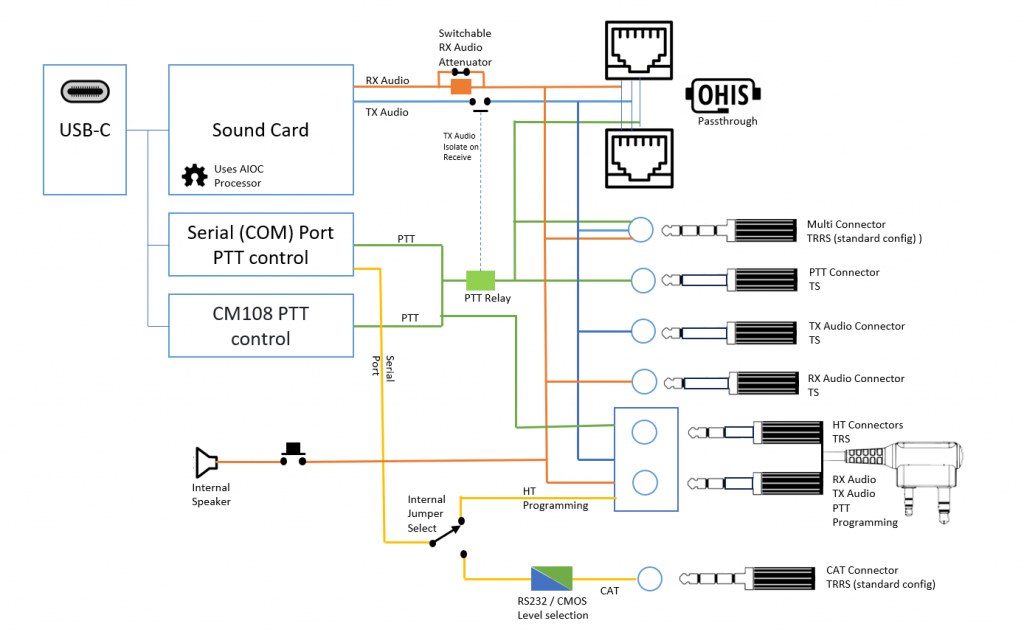
The latest version (V2.2) of this multi-port ‘universal’ radio controller is a versatile device that sits between your computer and transceiver.
The unit provides the following functions:
- USB-C sound card to connect your radio to a computer
- Full PTT control using either serial port settings (DTR & CTS) or the CM108 standard.
- CAT (Computer Aided Transceiver) control for transceivers to allow real-time management of band, frequency and PTT etc.
- Serial connection to HTs (Handy Talkies) for serial port programming with CHIRP, or the manufacturers software.
The URC is housed in a 100x88x38mm enclosure with custom silk-screened front an back panels.


The Connections to the radio are via a variety of connection types:
- 3.5mm multi-connector (RX Audio, TX Audio & PTT)
- 3.5mm individual connectors for RX Audio, TX Audio & PTT
- OHIS connectors for RX Audio, TX Audio & PTT
- Two-pin Handy-Talkie (HT) connector for RX Audio, TX Audio & PTT (& programming)
Further expansion of connections and functions is facilitated by an internal expansion connector to support ‘personality boards’.
USB Connection
The unit is connected to the host and powered by a USB-C connector.
Through the USB the URC emulates a mono sound card and a serial interface for use by software. The unit also emulates the CM-108 soundcard PIO functions for PTT control (the CM108 PIO input is not supported for e.g. for COS detection).
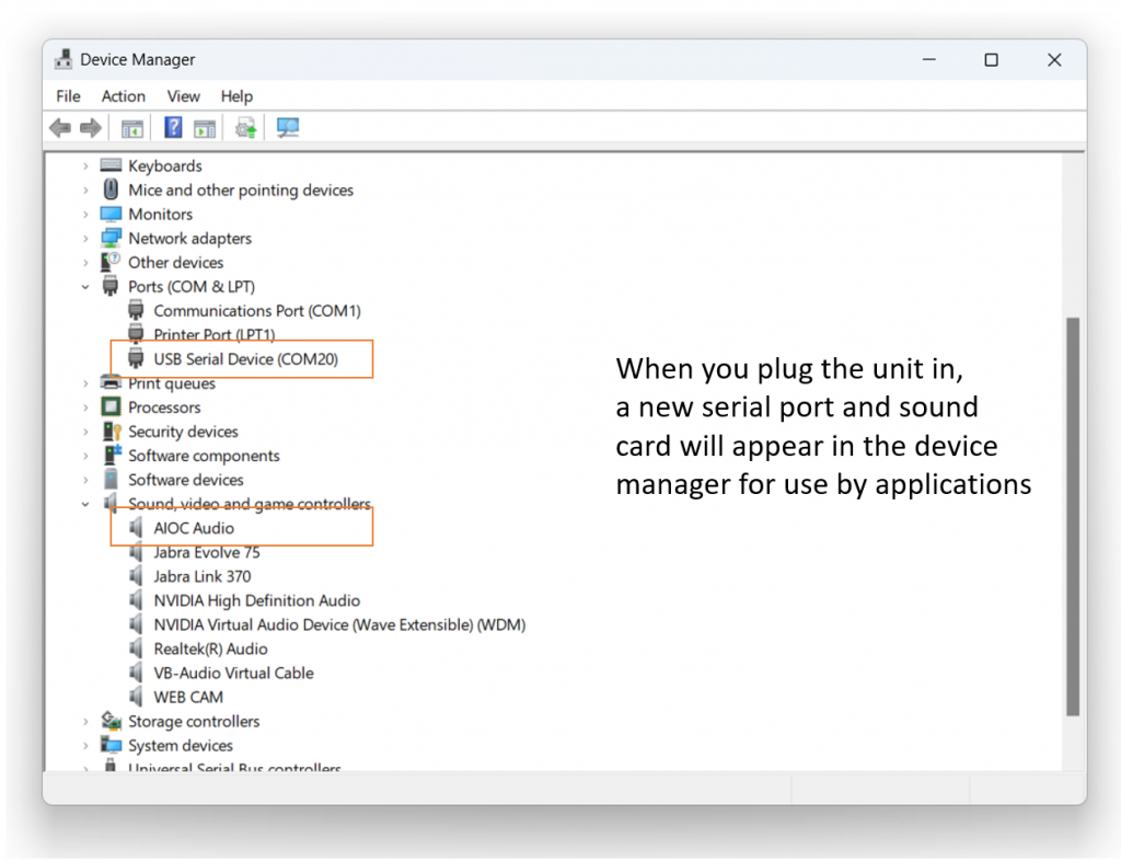
Additional drivers are not needed for modern operating systems (Windows, Linux etc).
Incompatibilities have been encountered with some external USB hubs, so it’s best to directly connect the URC to the main USB ports of the computer host.
Sound card emulation
The sound card interface of the unit gives access to the audio data channels. It has one mono microphone channel and one mono speaker channel and currently supports the following bit rates:
48000 Hz (preferred)
32000 Hz
24000 Hz
22050 Hz (specifically for APRSdroid, has approx. 90 ppm of frequency error)
16000 Hz
12000 Hz
11025 Hz (has approx. 90 ppm of frequency error)
8000 Hz
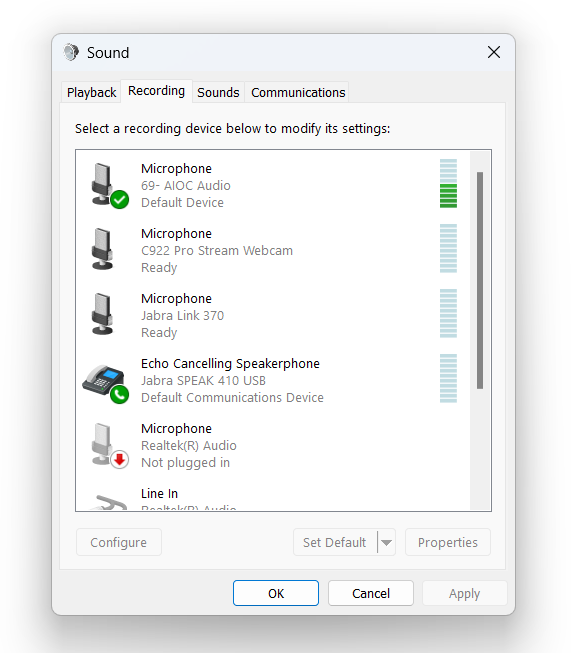
The sound card can be identified by the AIOC name in device manager and system settings.
PTT control
PTT can be asserted in one of several ways:
- Directly by using the URC Com Port in the application and setting DTR=1 and RTS=0
- Directly by using the CM108 HID port functionality (supported by DireWolf etc)
- Indirectly by using the CAT port to signal PTT to a transceiver (see CAT control below)
An internal PTT relay connects the PTT line of the connectors (excluding the HT Two-pin connectors) to ground on transmit. The use of a physical relay provides robust and reliable control of a variety of transceivers and other equipment
TX Audio & switching
TX Audio is at ‘electret’ levels (~10mV) for direct connection to the Mic port of a transceiver.
On pre-2024 models, TX Audio is electrically isolated from the ‘Multi’, ‘TX Audio’ and OHIS connectors until the PTT relay is activated. TX Audio is not isolated from the HT two-pin ports in this way, so VOX functions on HTs can be used if desired.
For applications where TX Audio is required without engaging the TX relay (e.g. when using PTT over CAT) then the solder jumper ‘VOX-EN’ on the main board should be bridged.
For models shipping from 2024 onward, this is reversed so the VOX-EN jumper is bridged and should be cut if needed.
TX Audio isolation is included to remove load from the OHIS bus when the URC is not in PTT mode, so if you are not using the unit for OHIS bus applications, then permanently connecting TX audio with this jumper should not cause any problems.
RX Audio & monitor
RX Audio is designed to operate at Loudspeaker levels (typically a volt or two).
If you are using a radio ‘line-level’ output or a pre-emphasis output (~0.3v) then the analogue to digital converter in the unit may not have sufficient signal for your digital application.
There is a jumper on the main board to adjust the attenuator, this has a ‘0 attenuation’ setting to provide the maximum signal level to the URC input stage.
Use your computer sound card settings to view and adjust the attenuator for optimal range. Avoid over driving the input as this will distort the signal and lead to errors.
The URC includes a ‘monitor’ function that routes attenuated RX Audio to a small front panel speaker. The monitor function is designed form occasional monitoring of the RX Audio line where the URC is plugged into the radio’s speaker port. The monitor speaker will load the RX Audio line and reduce the level on the soundcard input whilst the monitor button is pressed.
The main board includes the facility to solder in a load resistor for radios that do not like to drive a speaker output without a load. This is seldom required.
OHIS
The Open Headset Interconnect Standard (OHIS) is actively being developed by Mark N6MTS. Information is available at https://ohis.org/
The connector standard for OHIS is the robust and familiar RJ45 (aka 8P8C Modular) plug. The selection of this standard is great for low-cost and availability of cable, plugs and general mounting hardware.
The URC has two OHIS connectors wired in parallel on the rear of the unit. This allows the URC to be placed in-line as a User device, between the transceiver and the microphone.
The OHIS connector provides duplicate connections to the ‘Multi’ jack socket on the front panel.
For the URC implementation of the OHIS connector, the VCC line is not connected within the unit, but is passed between the two ports. The RX Audio is connected to the Left OHIS RX Audio (L) line only.
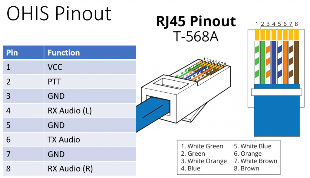
The OHIS standard outlines that separated grounds for PTT, RX Audio and TX Audio should be used if possible. Within the URC this separation is not possible so the ground connections of pins 3-5-7 are connected in common.
Serial port function
The serial interface of the unit shows up as a regular COM (Windows) or ttyACM port (Linux) and can be used as such for regular serial port communication and PTT (Asserted on DTR=1 and RTS=0).
Typically the serial port function is selected to route to the front panel HT sockets for programming radio’s using CHIRP etc. or is routed to the rear port CAT connector. The selection is via internal jumpers on earlier URC models or via a front panel slide-switch on later versions.
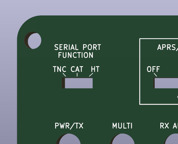
Where a front panel switch is present, a third position may be used to route the serial port function to the ‘personality board’ to control the in-board peripheral e.g. a TNC/APRS modem or the WinKeyer control port.
The serial port provides RX data and TX data only, CTS, DCD etc, are not available for use.
CAT (Computer Aided Transceiver) control
A 3.5mm rear panel jack socket provides CAT control. This is presented as a 3.5mm TRRS jack socket.
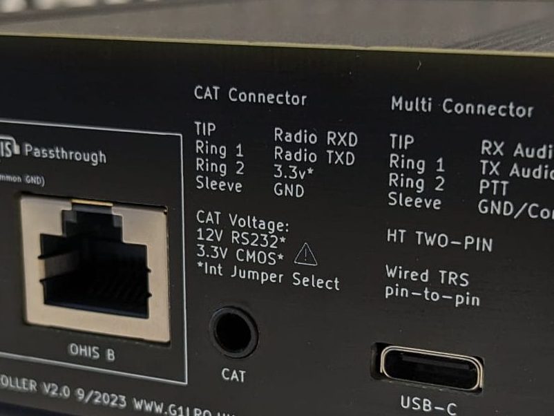
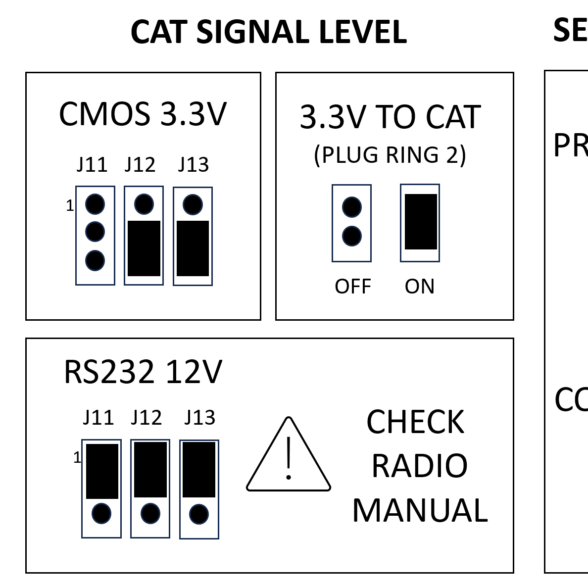
Using internal jumpers, the serial levels on the CAT are selectable between 3.3v CMOS levels (default and most popular), and 12v RS232 levels.
Using 12v levels on a transceiver that’s expecting 3.3v can cause serious damage to the transceiver – be careful.
For radios that support the half-duplex CI-V standard using just one wire for serial transmit and receive, this is supported by the URC and a configuration is documented below .
A 3.3v low-current supply is available on the CAT connector, but by default the internal jumper for this is not enabled the URC. Only enable this under guidance from your transceiver provider. This 3.3v line is fed via a 110R current limiting resistor.
Main board jumpers

- A: PROG jumper
This jumper is provided for applying firmware updates to the URC main processor.
The default is to have the jumper removed. Only install this jumper whilst loading firmware to the processor.
Later models of the URC have a PROG button instead of the jumper. Hold down the button whilst applying power to the URC to enter programming mode. - B: RX AUDIO ATTEN
This 3-pin jumper provides multiple levels of attenuation to the signal feeding the URC input stage.
A small graphic on the board shows the 3 configurations of the jumper. The ‘0’ setting is for no attenuation and provides the maximum level of signal to the URC sound card processor.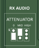
- C: J15 Serial Port function
This 3-pin header provides the routing of the serial port to the front panel HT programming function or the rear CAT serial port.
On later models this is replaced by a front panel switch and no jumper should be installed (the jumper may not be populated in the board). - D: 3.3V to CAT
This jumper is not installed by default.
Asserting this jumper will supply low current 3.3v to Ring-2 on the CAT connector. - E: J11, J12, J13 Serial Port levels
These three physical jumpers set the voltage characteristics of the serial port, primarily between 3.3v CMOS levels (default) and 12v RS232 levels.
Only select 12v levels if you are sure they are required. - F: VOX-EN
This solder jumper routes TX Audio permanently to the front panel and OHIS connectors. See TX Audio section above for information. - G: STEREO
This solder jumper connects Ring-1 of the RX Audio socket to the TIP. This effectively connects Left and Right audio of a stereo jack cable to the URC input.
If you are using mono plugs, bridging this jumper will connect the tip and sleeve of your RX audio, grounding the audio input. Not desired.
Typically RX Audio is a mono signal, presented on the Tip only of the cable.
A secondary application of this jumper is for the WinKeyer personality board that presents the side-tone to the RX Audio line. If stereo headphones are plugged into the RX Audio jack then this jumper provides the CW side tone to both ears. - H: MONITOR LEVEL SELECT
This 4-position jumper was supplied to change the volume level of the front-panel monitor speaker.
This level selection does not have an effect on speakers connected to a personality board (they have a separate resistor on the board)
Later versions of the URC have speakers exclusively connected to a personality board and this jumper has been removed.
CI-V serial port configuration
Some radios such as the Icom IC-7000 use a CAT cable that has both TX and RX data wired together to the tip. This means the serial communication is half-duplex and additional circuitry is needed to handle this configuration.
The URC has the circuitry needed but the serial port jumpers need to be wired in a specific configuration.
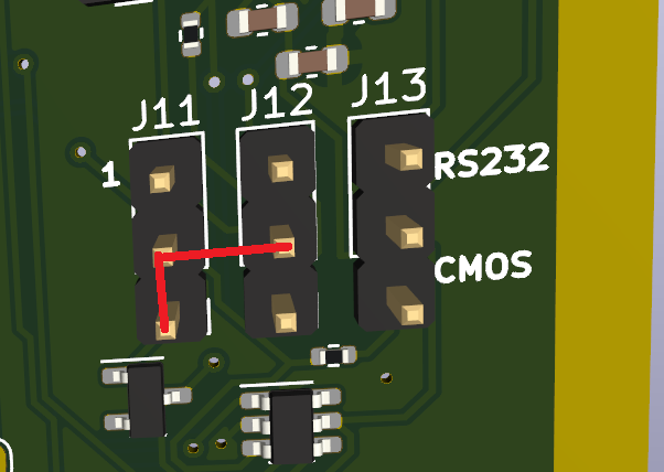
Connect 3 pins on J11 & J12 as in this diagram. Jumpers won’t quite work here as J11(2) has to be connected to two pins. A suggestion is to make up a custom wire from some breadboard wires with 3 Dupont connectors to go over the pins .
Remove the jumper on J13 entirely.
Internal Modem Expansion Port
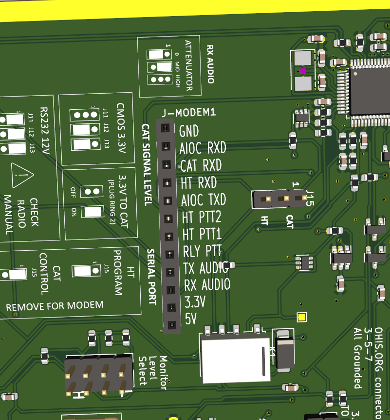
Version 2.2 of the URC brough the internal J-MODEM1 connector. This connector provides the essential signals to a range of ‘personality boards’ that expand the functionality of the URC.
Later versions of the URC use the modem connector to provide the front panel Monitor and Serial port switch through the use of a basic connector board.
The modem connector and board standard has been released as Open-Source Hardware to allow innovators to produce new and interesting personality boards for the URC. See this link https://github.com/G1LRO/universal-radio-controller