
This guide is aimed at creators who are interested using the main board features of the URC for new in innovative applications.
The J-MODEM1 connector on the URC main board was added in to the main design to provide the capability to accommodate ‘Personality Boards’ to make use of the URC functionality. Since the entire front panel and rear panel space had been used for the wide range of connectors supported by the URC, the only option was to go up and add an additional board layer for new functionality.
The information below gives guidance to designers of new functionality. An open-source hardware repo will be published with physical design information for the personality board dimensions and front panel template.
Pin Descriptions:
| Pin | Function/specification |
|---|---|
| 1 | Ground Notes: Common ground for audio, power and serial |
| 2 | Serial data TO the AIOC processor Notes: This connects to the the receive pin on the processor via 220R resistor Levels are CMOS level (max 3.3v) Diode protection is present on the URC main board see Note 1 See Note 3 |
| 3 | Serial data FROM the CAT port Notes: This provides signals receive pin rear CAT port via a non-inverting buffer. Levels are CMOS level (max 3.3v) See Note 3 |
| 4 | Serial data FROM the front panel HT connector. Notes: This provides unbuffered signals from the Ring-1 of the 2.5mm HT jack. Levels are CMOS level (max 3.3v) although subject to the radio specification. See Note 3 |
| 5 | Serial data FROM the AIOC processor Notes: The transmit pin on the processor operates at CMOS level (max 3.3v) Diode protection is present on the URC main board see note 1 Serial Data from the AIOC process is not switched by the front panel switch so will be simultaneously presented on the Rear CAT connector via a non inverting buffer and via non-inverting buffer to the HT 3.5mm Tip via 220R resistor for HT programming . |
| 6 | PTT function of HT Note: Connected to Sleeve of 3.5mm HT socket Should be transistor-switched to ground – See Note 2 |
| 7 | Secondary PTT function of HT Note: Recommended to leave disconnected with option to have transistor-switched as pin 6. – See Note 2 Connected to Tip on 3.5mm HT TXD is also present on this pin via 220R resistor |
| 8 | PTT Relay Note: Connected to the Base of BC847 via 2k2 resistor, switching PTT relay – See Note 4 Active high PTT relay switches the PTT line of all connectors except HT |
| 9 | Transmit Audio Note: Routes to the Mic pins on URC ports including HT Electret level (~10mv) All TX Audio connections are individually decoupled from this line via 4u7 capacitor. Soundcard Audio will also be present on this line via 10K resistor when the PTT relay is asserted. A 220R and 100n capacitor to ground are present on this line when the PTT relay is asserted. See Note 5 |
| 10 | Receive Audio Note: Routes to the Mic pins on URC ports including HT All RX Audio connections are individually decoupled from this line via 4u7 capacitor. Loudspeaker level – around a volt or two Feeds into input attenuator of AIOC processor Diode protection is present on the URC main board after the attenuator see Note 6 |
| 11 | 3.3v Note: Low current (20mA max) supply to reference to the AIOC CPU analogue to digital converters. Avoid use for supporting application devices Use an independent 3.3v regulator for application devices powered from 5v on pin 12. |
| 12 | 5V Note: Connected to USB 5V line VIN via ferrite bead filter 150mA max |
Note 1

CPU serial port pins have Schottky diode protection to give limited protection to over-voltage and reverse-voltage.
Note 2

Example switching circuitry for HT using dual-transistor BC857BS device.
HT PTT2 line is generally not used but should be left as optional by means of solder-jumper.
Note 3

Include a front panel switch to select the serial port function between the HT, CAT and the add-in application. This should be included even if the created application does not use the serial port so the user can select HT and CAT.
Note 4
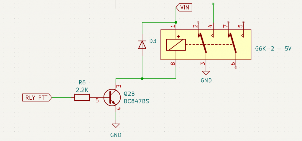
A dedicated transistor is present on the main board to switch the PTT relay. Apply logic-high to the RLY PTT line to activate the transistor and switch the relay
Note 5
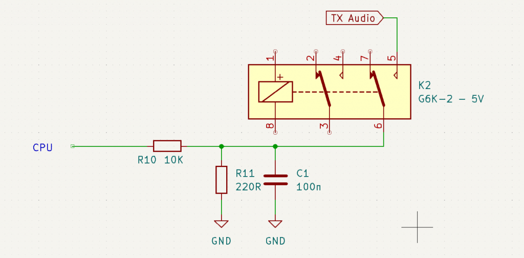
When PTT relay is asserted a 220R and 100n is present on the TX Audio line. The CPU sound-card output may be active also.
Note 6

The RX Audio input to the AIOC processor is routed via a jumper to select 3 levels of attenuation. Diode protection guards against over voltage and reverse voltage. Ensure signals to the RX Audio line are decoupled to allow the biasing of the CPU input at the midpoint by R7 & R8.