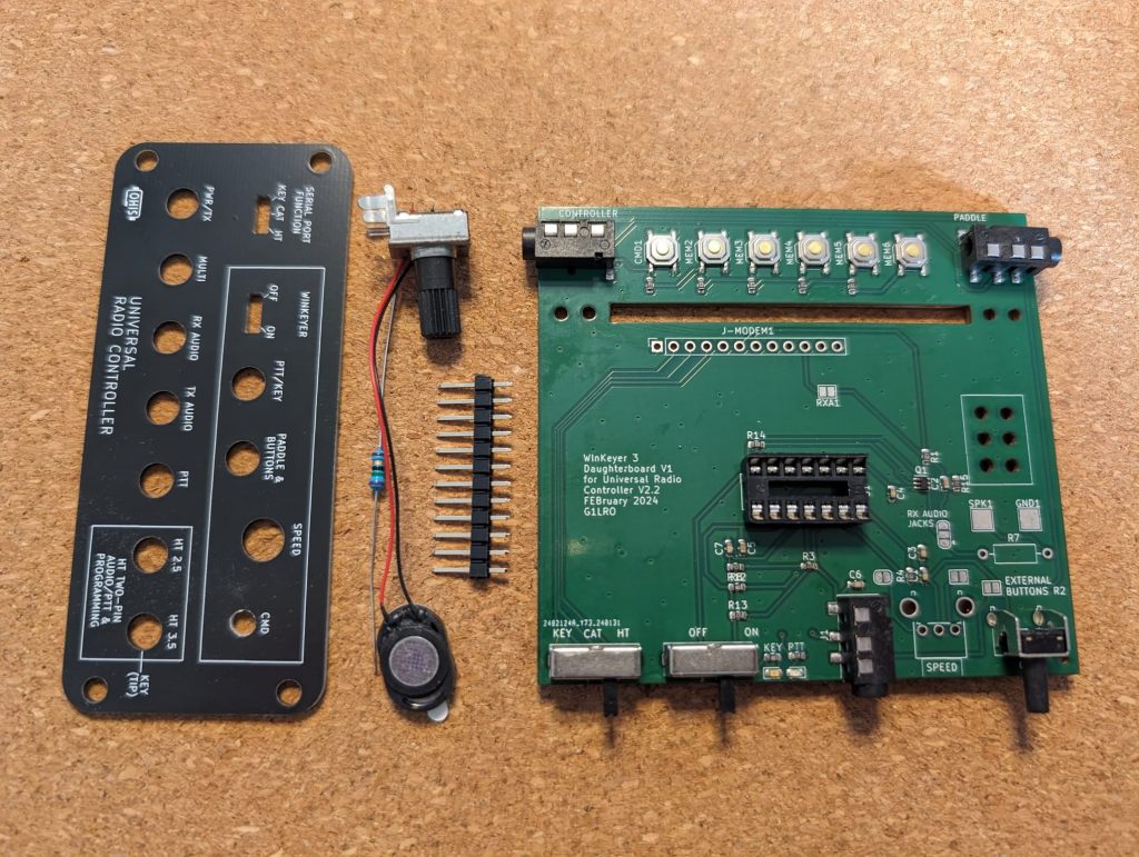
The WinKeyer personality board kit requires a little assembly before use.
There are 4 components to install on the board:
- 75 Ohm resistor
- Potentiometer
- 12-pin header
- Loudspeaker
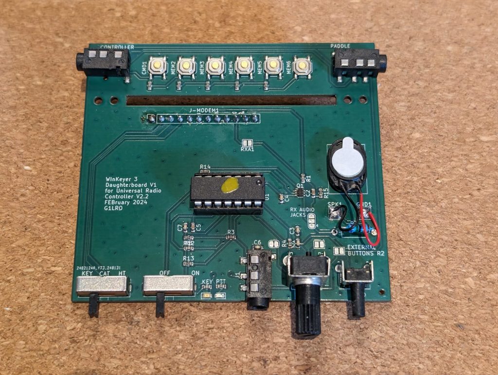
The following pictures show the board fully assembled:
Construction notes:
A fairly hot iron is needed to solder the potentionmeter supports into place as there’s a lot of metal to heat up.
The 75 Ohm resistor provided is to set the volume of the internal speaker for the CW side tone. Change this if desired but if you replace this then keep the value above 22 Ohms to limit current through the output transistor.
Solder the speaker wires to the surface pads marked SPK1 and GND1 then use the self-adhesive pad on the speaker to fix it within the area marked on the board facing down.
It may be helpful to install the WinKeyer board in the case before soldering the 12-pin header, to ensure good location.
NOTE: the WinKeyer board front panel jack is configured for a two way paddle on Tip and Ring1 of the jack with the sleeve as ground. The left and right paddles can be swapped in the software.
Board Configuration Options:
There are 4 solder jumpers on the board to allow management of features:
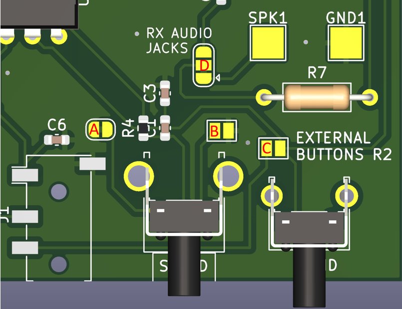
A & B – These jumpers control the direction of the potentiometer. To reverse the direction, cut though the track bridging Jumper A and place a solder bridge across Jumper B.
C – External Buttons R2: This jumper connects the jack socket Ring 2 connection to the input of a 6 button board. The specification of the button board is on page 23 of the WinKeyer 3 Datasheet. If this jumper is bridged, a TRRS plug must be used on the WinKeyer front-panel paddle jack (a TRS jack will ground the external buttons line on ring 2 and cause a malfunction)
D – Headphone output on RX Audio front panel jack. To have CW side tone on headphones installed in RX Audio jack on the front panel of the URC, bridge the upper link of this jumper. To disable the internal speaker, cut the lower link of this jumper (the center and the pad with the small arrow). To use stereo headphones, review the technical reference on https://g1lro.uk/?p=330 regarding the ‘Stereo’ jumper on the main board.
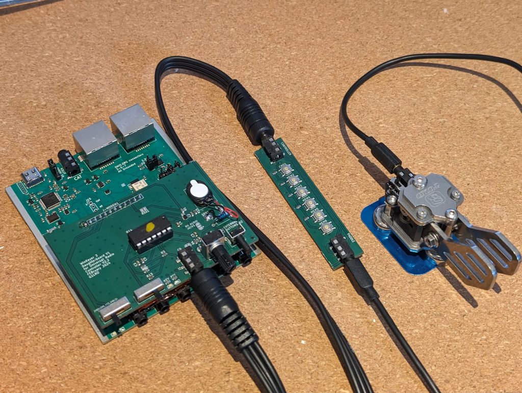
External Button Board
Later versions of the WinKeyer personality board have a basic button board attached to the rear. Although this button array will fully work as shipped, this button board needs removing before the URC case can be reassembled. Use cutters to snip the button board from the main board, cutting through the existing tracks.
If the button board is to be used then a TRRS (4 pole) cable is needed to connect the button board to the WinKeyer board, also the Jumper C (see above) should be bridged with a blob of solder. The button board has a separate socket for the key that will be connected via the standard ‘stereo’ type TRS plug.
Note: with Jumper C bridged then a paddle cannot be directly inserted into the Winkeyer with a stereo 3 pole plug as it will short the Ring 2 for the buttons, and upset the Winkeyer processor (don’t worry, it won’t damage it). A custom cable can be made for directly inserting the paddle into the Winkeyer if the Jumper C is bridged, leaving Ring 2 disconnected at the Winkeyer end.
Creating the font panel LED diffusers:

The front panel diffusers are created using the method above. The diffuser bungs can easily be moved between front panel boards.
Software
With the K1EL WinKeyer 3 installed and the unit connected to a PC, a serial port will be available in the device manager:
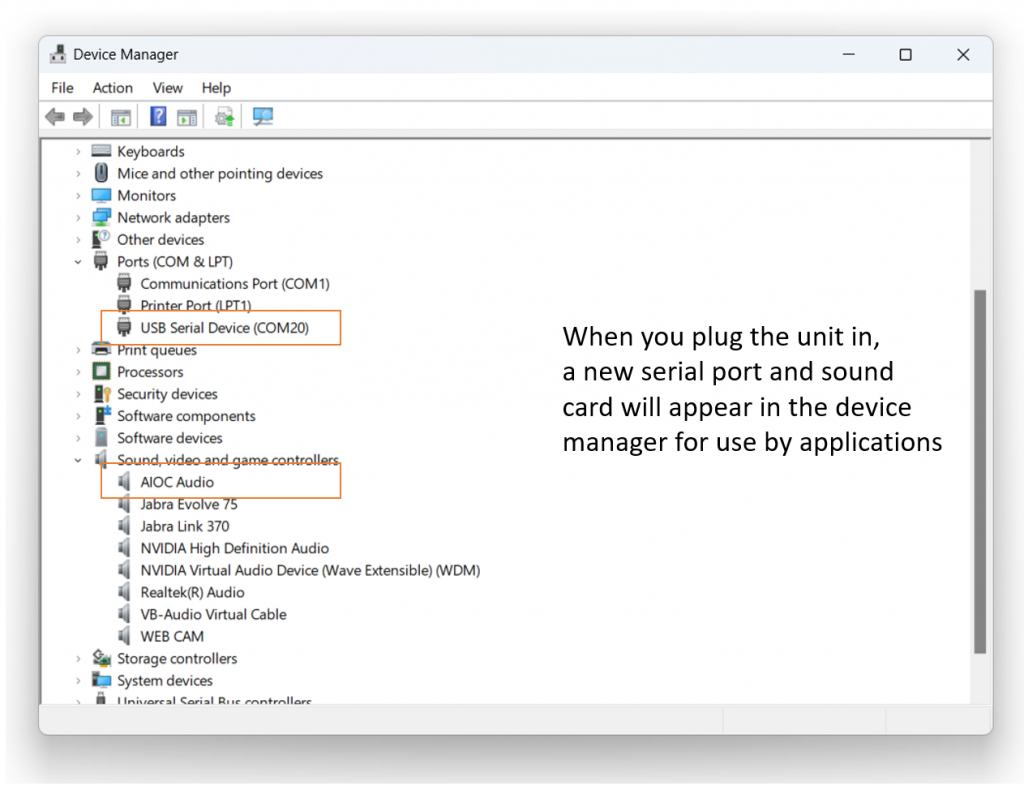
Note the number of the serial port and move the serial port selection switch on the front of the URC to the ‘KEY’ setting.
Use the WK Scan utility to check the WinKeyer is recognized by windows: LINK
Use the WK Demo utility to explore features of the Winkeyer: LINK
Explore the K1EL software library for other features and functions: LINK
Connecting to a Radio
The WinKeyer provides a separate PTT and KEY output function, these are presented on two jack sockets on the front panel. Most modern transceivers only need a KEY function, so a custom cable needs to be made as shown below. The PTT function would be used to key an external power amplifier so to keep it in transmit during a CW session.
Always consult your transceiver documentation for wiring information and operation of the CW jack.
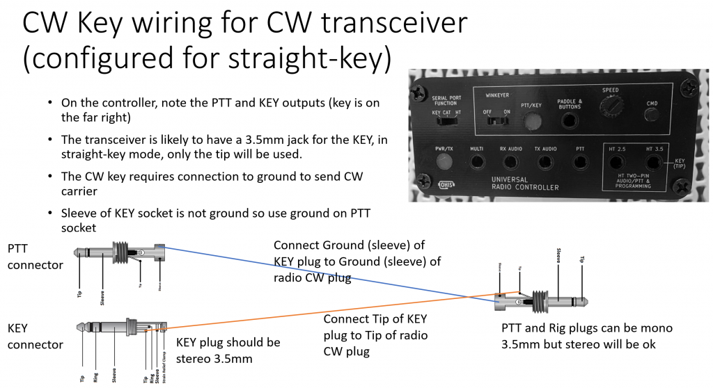
You may need to configure your transceiver to use a traditional straight key (not a paddle key) to use the WinKeyer correctly.
Further reading
The WK3 processor is covered in full detail in the datasheet, including a comprehensive command reference guide:
Download WK3 datasheet from K1EL systems